
Voltage Divider Theory
Fundamental Principle
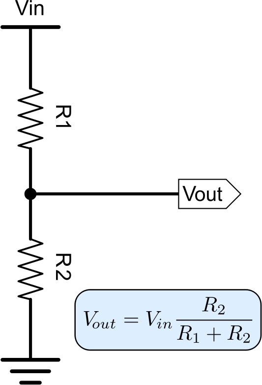
A voltage divider is a passive linear circuit that produces an output voltage (Vout) that is a fraction of its input voltage (Vin). It consists of two resistors, R1 (top) and R2 (bottom), in series.
Real-Time Usage
- Level Shifting: Converting 5V sensor signals to 3.3V for ESP32/STM32 pins.
- Battery Monitoring: Reducing high battery voltage (e.g., 12V) to a safe range (0-3.3V) for an ADC.
- Sensor Reading: Using a variable resistor (like an LDR) as R1 to measure environmental changes.
Smart Multi-Way Calculator
Enter any three values. Leave one field blank to solve for it.
💡 Pro-Tip for Guruvel Creativities
The Loading Effect: Always remember that the device you connect to Vout has its own resistance. To ensure a stable voltage, your divider resistors should be at least 10x smaller than the input impedance of the connected device. For general microcontrollers, 10kΩ is the industry standard "sweet spot" for balancing power and accuracy.
Hi, I’m Guruvel Sarveshwar — a passionate creator behind Guruvel Creativities. I specialize in DIY electronics, IoT systems, 3D printing, and web-integrated smart projects. With a drive to innovate and share knowledge, I love turning ideas into reality through practical engineering and creative design.
Contact Me

0 comments:
Post a Comment
Thanks For Visiting