Introduction:
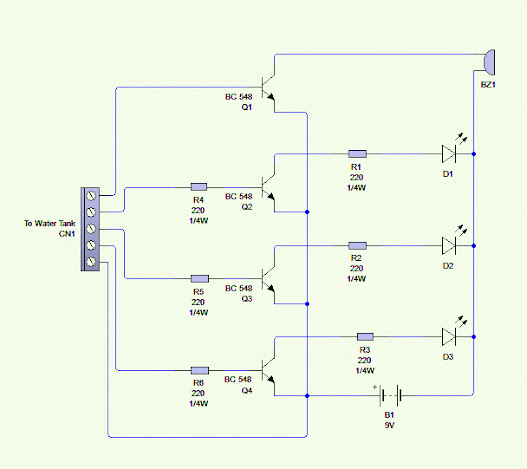
Welcome to the "Water Level Indicator Circuit" project, a design employing transistors to indicate water levels. This circuit functions akin to the Continuity Tester Circuit, activating the LED of the corresponding transistor when continuity is established between the +ve pin and the "n"th transistor. The entire circuit operates based on this principle.
This is the simple version of water level controller circuit using NE555 Timer IC.
Connection:
The connections for this circuit are simple once the transistor's pinout is understood. The BC 548 Transistor has three pins: the 1st Pin is the "Collector" pin, the 2nd Pin is the "Base" pin, and the 3rd Pin is the "Emitter" pin. The Collector Pin of the 1st Transistor is directly connected to the +ve of the Buzzer, while the Transistor's Base is linked to the Tank's Overflow Level Wire. The Transistor's Emitter is connected to the +ve of the Power Supply. The Collector Pin of the 2nd Transistor is serially connected to a 220Ω Resistor to the Green Color LED, with the Transistor's Base linked to the Tank's Upper Level Wire. The Transistor's Emitter is connected to the +ve of the Power Supply. Similarly, the 3rd Transistor's Collector Pin is serially connected to a 220Ω Resistor to the Yellow Color LED, and the Transistor's Base is linked to the Tank's Middle Level Wire. The Transistor's Emitter is connected to the +ve of the Power Supply. Finally, the Collector Pin of the 4th Transistor is serially connected to a 220Ω Resistor to the Red Color LED, and the Transistor's Base is linked to the Tank's Low or Bottom Level Wire. The Transistor's Emitter is connected to the +ve of the Power Supply. All Transistor's Emitter Pins are commonly connected to the +ve of the Power Supply. The Power Supply's +ve wire is connected to the surface common wire. All LEDs and the Buzzer's -ve are commonly connected to the -ve of the Power Supply.
Circuit Diagram:
Working:
Apply power supply to the circuit and connect all water level terminals to the water tank. As the water level touches the +ve of the 1st Transistor's Base Level, the Red Color LED turns on. When the water level reaches the 2nd Transistor's Base at the Middle Point, the Yellow Color LED illuminates. As the water level reaches the 3rd Transistor's Base at the Upper Level Point, the Green Color LED activates. Finally, when the water level reaches the overflow point, the buzzer produces a sound. As the water recedes, the LEDs turn off one by one.
Part
List:
1) BC
548 Transistor =4
2) 220Ω
¼w Resistor =6
3) Buzzer
=1
4) Red
LED =1
5) Green
LED =1
6) Yellow
LED =1
7) Some
Connectors
8) Zero
Board =1
9) 9
Volt Power Supply =1
10) Some
Wires
Uses
of the Circuit:
This Circuit is used to measure the level of the tank on the upper part of the building.
Click Here to Watch the YouTube Video for this Article:
By,
G.
Guruvel Sarveshwar,
EEE
Dept.


0 comments:
Post a Comment
Thanks For Visiting