Introduction:
Circuit Connections:
The circuit for this NodeMCU Blynk Home Automation project is Simple. Here I have used an active low 5V relay module and Some Jumper Wires. First of all, Fit the NodeMCU on the Bread Board. Then Connect the NodeMCU’s Vin Pin to the Upper Row of the Bread Board and Ground to the Lower Row of the Bread Board. These Two Terminals are the Input Power Supply Wires. Then Take the 5V Relay Module and Connect the Relay Module’s Power Supply Wires to the Input Power Supply Wires. Then Connect the Relay Module’s 1st Input Pin to the D1 and then the 2nd Input Pin to the D2 of the NodeMCU. Then Check the Connections One More Time Before Giving the Power Supply. Thus Circuit Connections were Fulfilled.
Circuit Diagram:
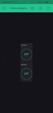
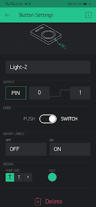
Blynk Application InterFacing:
Download the Blynk Legacy (Old Version)
Application from the Play Store.
Click Here to Download
After Finishing the Above Steps,
Upload
the Below Project Code into the NodeMCU, by Following Steps in Our Video.
Project Code:
Working:
We Control this Project with the Help of an External Wi-Fi source and Blynk Application. The Blynk Application will be connected through the Authentication ID. This Authentication ID is Send to Your Mail ID Registered on Your Facebook Account. This ID is Very Important for Uploading Code and Project Working. When Your NodeMCU is Connected to the Power Supply and then Connected to the Wi-Fi, Thus the Board Symbol is not showing Offline Symbol. Thus Controls Will be Command by the Mobile
Controlling AC Lamps with Wi-Fi:
Now we can control these AC lamps or any other home appliances from the smartphone. So this is a simple but Useful internet of things project which I can control the home appliances from anywhere if I have an internet connection on my mobile.
I hope, you like this IoT-based project with NodeMCU.
Part List:
1) NodeMCU ESP-8266 Module =1
2) 5 Volt Relay Module =1
3) Bread Board =1
4) Some Wires =1
5) Input Power Supply =1


0 comments:
Post a Comment
Thanks For Visiting