
Introduction:
Welcome to the Rain Alarm Circuit project, powered by the NE 555 Timer IC. This versatile circuit is simple in design and can be used for multiple purposes such as a water overflow alarm and a rain alarm. Here, we'll walk you through the steps to create this rain alarm circuit.
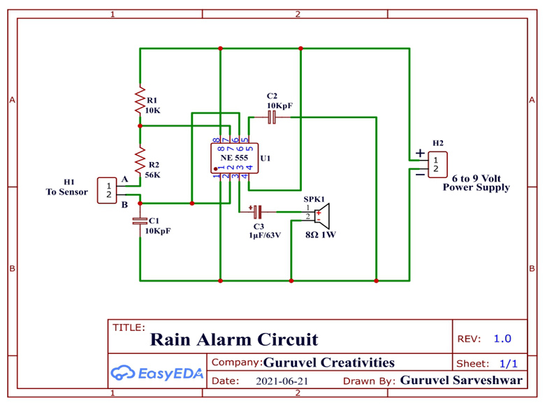
Connection Instructions:
Placement of Components:
- Place the NE 555 Timer IC with an IC Base at the center of the DOT/ZERO Board.
Resistors:
- Solder a 10KΩ resistor and a 56KΩ resistor serially on the left side of the IC.
- Connect the 7th pin of the IC between the 10KΩ and 56KΩ resistors.
Sensor Connections:
- The 2nd pin of the 56KΩ resistor leads to the 1st pin of the sensor.
- Connect the 1st pin of the capacitor (10KpF) to the 2nd pin of the sensor, which is made using a PVC or copper sheet.
Capacitors:
- Connect the 2nd pin of the 10KpF capacitor to the -ve of the power supply.
- Link the 6th and 2nd pins of the NE 555 IC to the +ve (1st pin) of the capacitor.
Power Supply:
- Connect the 1st pin of the 10KΩ resistor to the +ve of the power supply.
- Connect the 4th and 8th pins of the IC to the +ve of the power supply wire.
- Connect the 1st pin of the IC to the -ve of the power supply.
- The 5th pin of the IC should be connected serially to the 10KpF capacitor, which is then connected to the -ve of the power supply.
Output:
- For the output, use an 8Ω speaker.
- Connect the +ve pin of the 1μF/63V capacitor to the 3rd pin of the IC.
- Connect the -ve pin of the capacitor to the 1st pin of the speaker.
- The other pin of the speaker should be connected to the -ve of the power supply.
Circuit Diagram:
Working:
The circuit operates based on the Continuity Tester Circuit principle. When continuity is established between terminals A and B (due to rainwater), the circuit switches from an open state to a closed state:
- The +ve supply flows through the 8th and 4th pins of the IC.
- The -ve supply flows through the 1st and 5th pins of the IC.
- When the power supply reaches the IC, an output voltage emerges from the 3rd pin.
- This voltage is converted into an audible signal by the connected capacitor, which is amplified and sent to the speaker.
For a simpler setup, a buzzer can replace the speaker and capacitor combination.
Part List:
1) NE 555 Timer IC =1
2) 8 Pin IC Base =1
3) 1μF/63V Capacitor =1
4) 10KΩ ¼ W Resistor =1
5) 56KΩ ¼ W Resistor =1
6) 8Ω 1W Speaker =1
7) 10KpF Disc Capacitor =2 (102)
8) Some Wires
9) DOT Board =1
10) 2 Pin Connectors =2
Uses of the Project:
This project is designed to alert you during rain and has various applications, such as:
- Rain Alarm
- Water Level Alarm
- Fire Alarm
By following the steps outlined above, you can create a reliable rain alarm system using the NE 555 Timer IC. This circuit can be adapted for various alerting purposes, providing flexibility and utility in different situations.
Hi, I’m Guruvel Sarveshwar — a passionate creator behind Guruvel Creativities. I specialize in DIY electronics, IoT systems, 3D printing, and web-integrated smart projects. With a drive to innovate and share knowledge, I love turning ideas into reality through practical engineering and creative design.
Contact Me

0 comments:
Post a Comment
Thanks For Visiting